이 글은 로봇만들기 재능봉사단에 사용될 자료입니다.
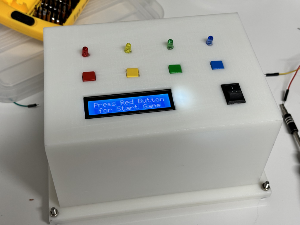
이번 시간에는 기억력 테스트 게임기를 만들어볼겁니다.

LED에 순차적으로 불이 들어오고, 단계가 늘어날 수록 기억해야할 색깔 순서가 늘어나게 됩니다.
단계별로 순서를 외워서 동일한 색상의 버튼을 차례대로 눌러주면 됩니다. 최대 몇 단계까지 외울 수 있을까요?
이번 작품을 만들기 위해서 사용될 부품은 아래와 같습니다.
준비물
| NO | 부품명 | 수량 |
| 1 | 아두이노 UNO R3 | 1 |
| 2 | LCD모듈 | 1 |
| 3 | LED | 4 |
| 5 | 저항(100옴) | 4 |
| 6 | 택트스위치(노브) | 4 |
| 7 | 부저 | 1 |
| 8 | 점퍼케이블 | 25 |
| 9 | 9V 전원(케이블) | 1 |
| 10 | 브레드보드 | 1 |
택트 스위치에 대해서 알아봅시다. 아두이노 핑퐁게임 만들기에서 이미 한번 배운 적이 있는데 복습을 해볼까요?

버튼을 누름으로써 접점을 개폐하는 스위치를 푸쉬버튼 스위치라고 하며 상단에 단추 모양의
버튼과 하단에 4 개의 단자로 구성되어 있습니다.
상단 버튼은 힘을 가하여 접점을 개폐하는 역할을 하며, 하단의 단자는 회로와
스위치를 연결하는 다리 역할을 합니다.
단자 연결은 마주보는 단자끼리 서로 연결되어 있어 한 쌍으로 구성됩니다.
아래 사진으로 예를 들면 기본상태에서는 서로 마주보고 있는 A 와 D 가 서로
연결되어 있고 B 와 C 가 서로 연결되어 있습니다.

버튼을 누르지 않은 상태에서는 A, D 와 B, C 는 서로 떨어져 있지만 버튼을 누르게
되며 접점이 닿게 되어 A, D 와 B, C 가 서로 연결됩니다.
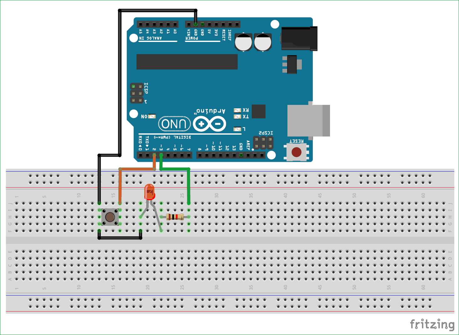
스위치로 LED를 On/Off하도록 아래와 같이 회로도를 구성하고 코드를 업로드하여 확인해봅시다.

void setup() {
pinMode(2,INPUT_PULLUP);
pinMode (3,OUTPUT);
}

void loop() {
  if (digitalRead(2) == LOW)
  {
    digitalWrite(3,HIGH);
  }
  else
  {
    digitalWrite(3,LOW);
  }
}
다음은 부저가 뭔지 알아봅시다.

아두이노에서 사용되는 부저는 소리를 발생시키는 장치입니다. 부저는 전기적 신호를 받아서 진동을 발생시켜 소리를 내는데, 이는 일반적으로 피에조 부저( Piezo Buzzer)라고도 합니다.
부저는 피에조 소자로 이루어져 있습니다. 피에조 소자는 압전효과를 이용하여 작동합니다. 압전효과란 일정한 압력이나 변형이 가해지면 이에 반응하여 전기적인 신호를 생성하는 현상을 말합니다. 피에조 부저는 부착된 피에조 소자에 전기적 신호(주로 주파수)를 가하면 소자가 변형되어 진동을 일으키게 됩니다. 이 진동은 주변의 공기를 압축하고 이완시켜 소리를 발생시킵니다.
아두이노에서 부저를 사용할 때는 디지털 출력 핀에 부저를 연결하고, 아두이노 코드를 사용하여 해당 핀으로 신호를 보내어 소리를 발생시킵니다. 주파수와 지속시간을 조절하여 다양한 소리를 만들 수 있습니다.
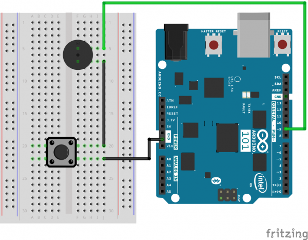
스위치로 부저를 작동시키는 테스트를 해봅시다. 아래와 같이 회로를 연결해주세요.

/*
SparkFun Inventor's Kit
Example sketch 14

BUZZER

  Use the buzzer to play a song!

This sketch was written by SparkFun Electronics,
with lots of help from the Arduino community.
(This sketch was originally developed by D. Cuartielles for K3)
This code is completely free for any use.
Visit http://learn.sparkfun.com/products/2 for SIK information.
Visit http://www.arduino.cc to learn more about Arduino.

*/

/*
This sketch uses the buzzer to play songs.
The Arduino's tone() command will play notes of a given frequency.
We'll provide a function that takes in note characters (a-g),
and returns the corresponding frequency from this table:

  note  frequency
  c     262 Hz
  d     294 Hz
  e     330 Hz
  f     349 Hz
  g     392 Hz
  a     440 Hz
  b     494 Hz
  C     523 Hz

For more information, see http://arduino.cc/en/Tutorial/Tone
*/

const int buzzerPin = 9;

// We'll set up an array with the notes we want to play
// change these values to make different songs!

// Length must equal the total number of notes and spaces

const int songLength = 18;

// Notes is an array of text characters corresponding to the notes
// in your song. A space represents a rest (no tone)

char notes[] = "cdfda ag cdfdg gf "; // a space represents a rest

// Beats is an array of values for each note and rest.
// A "1" represents a quarter-note, 2 a half-note, etc.
// Don't forget that the rests (spaces) need a length as well.

int beats[] = {1,1,1,1,1,1,4,4,2,1,1,1,1,1,1,4,4,2};

// The tempo is how fast to play the song.
// To make the song play faster, decrease this value.

int tempo = 150;


void setup()
{
  pinMode(buzzerPin, OUTPUT);
}


void loop()
{
  int i, duration;

  for (i = 0; i < songLength; i++) // step through the song arrays
  {
    duration = beats[i] * tempo;  // length of note/rest in ms

    if (notes[i] == ' ')          // is this a rest?
    {
      delay(duration);            // then pause for a moment
    }
    else                          // otherwise, play the note
    {
      tone(buzzerPin, frequency(notes[i]), duration);
      delay(duration);            // wait for tone to finish
    }
    delay(tempo/10);              // brief pause between notes
  }

  // We only want to play the song once, so we'll pause forever:
  while(true){}
  // If you'd like your song to play over and over,
  // remove the above statement
}


int frequency(char note)
{
  // This function takes a note character (a-g), and returns the
  // corresponding frequency in Hz for the tone() function.

  int i;
  const int numNotes = 8;  // number of notes we're storing

  // The following arrays hold the note characters and their
  // corresponding frequencies. The last "C" note is uppercase
  // to separate it from the first lowercase "c". If you want to
  // add more notes, you'll need to use unique characters.

  // For the "char" (character) type, we put single characters
  // in single quotes.

  char names[] = { 'c', 'd', 'e', 'f', 'g', 'a', 'b', 'C' };
  int frequencies[] = {262, 294, 330, 349, 392, 440, 494, 523};

  // Now we'll search through the letters in the array, and if
  // we find it, we'll return the frequency for that note.

  for (i = 0; i < numNotes; i++)  // Step through the notes
  {
    if (names[i] == note)         // Is this the one?
    {
      return(frequencies[i]);     // Yes! Return the frequency
    }
  }
  return(0);  // We looked through everything and didn't find it,
              // but we still need to return a value, so return 0.
}
다음은 LCD 모듈이 정상적으로 작동하는지 테스트해봅시다.
아두이노 라이브러리 매니저에서 아래의 라이브러리를 설치해줍니다.

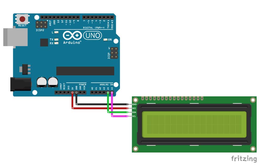
배선을 아래와 같이 해줍니다. SDA는 A4, SCL은 A5에 연결해줍니다.

/* I2C LCD with Arduino example code. More info: https://www.makerguides.com */

#include "Wire.h" // Library for I2C communication
#include "LiquidCrystal_I2C.h" // Library for LCD

// Wiring: SDA pin is connected to A4 and SCL pin to A5.
// Connect to LCD via I2C, default address 0x27 (A0-A2 not jumpered)
LiquidCrystal_I2C lcd = LiquidCrystal_I2C(0x27, 16, 2); // Change to (0x27,20,4) for 20x4 LCD.

void setup() {
  // Initiate the LCD:
  lcd.init();
  lcd.backlight();
}

void loop() {
  // Print 'Hello World!' on the first line of the LCD:
  lcd.setCursor(2, 0); // Set the cursor on the third column and first row.
  lcd.print("Hello World!"); // Print the string "Hello World!"
  lcd.setCursor(2, 1); //Set the cursor on the third column and the second row (counting starts at 0!).
  lcd.print("LCD tutorial");
}
LCD가 잘 작동하는지 확인해봅시다.
혹시나 네모모양만 나오거나 LCD 출력에 이상이 있을때에는 LCD 주소를 확인하는 코드를 이용해서 확인해봅시다.
/*I2C_scanner
  This sketch tests standard 7-bit addresses.
  Devices with higher bit address might not be seen properly.
*/

#include "Wire.h"

void setup() {
  Wire.begin();

  Serial.begin(9600);
  while (!Serial);
  Serial.println("\nI2C Scanner");
}

void loop() {
  byte error, address;
  int nDevices;

  Serial.println("Scanning...");

  nDevices = 0;
  for (address = 1; address < 127; address++ ) {
    Wire.beginTransmission(address);
    error = Wire.endTransmission();

    if (error == 0) {
      Serial.print("I2C device found at address 0x");
      if (address < 16)
        Serial.print("0");
      Serial.print(address, HEX);
      Serial.println("  !");

      nDevices++;
    }
    else if (error == 4) {
      Serial.print("Unknown error at address 0x");
      if (address < 16)
        Serial.print("0");
      Serial.println(address, HEX);
    }
  }
  if (nDevices == 0)
    Serial.println("No I2C devices found\n");
  else
    Serial.println("done\n");

  delay(5000);
}
