Today I will look at the Trajectory Planning Method for the Quadruped Robot Walking on Rough Terrain and explore the scenario where the quadruped robot walking on the rough terrain with the static walking gait.
COG(Center of Gravity) trajectory
Kinematic
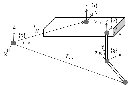
Let’s define planned walking patterns based on the position of the torso and foot. In order to realize this, joint angle calculation by inverse kinematics need. You can see the mechanical structure of the robot first manufactured.
In the figure, only one front right leg is shown. However, all legs had gimbals on their shoulders and hips. Pitch and roll direction 2 degrees of freedom that adopted structure, pitch room to knee With 1 degree of freedom, the robot has a total of 12 degrees of freedom.
Mechanism Model of the Quadruped Robot
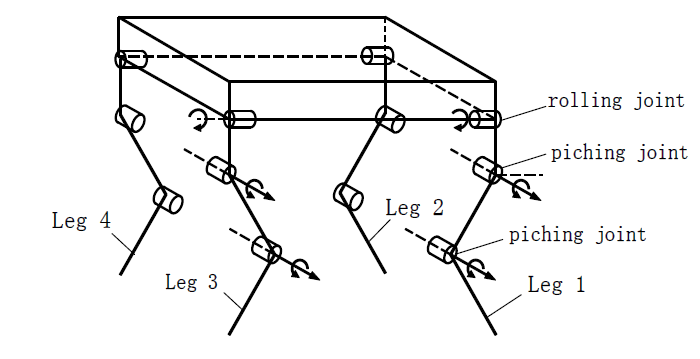
The quadruped robot has four legs, each leg with 3 degrees of freedom, a rolling rotary
joint and two pitching rotary joints, as shown above figure.
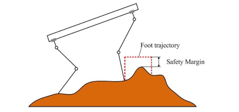
Foot Trajectory Planning
Foot trajectory planning is a fundamental part in the gait planning of the quadruped robot. The foot should move to the goal point exactly while avoiding any obstacle during the swing process, so it is very important to design an appropriate foot trajectory for the swing foot of the robot. If the complete terrain information is available for the robot, the movement trajectory for the swinging foot can be determined according to the terrain feature to get the optimum foot trajectory. But there is no onboard sensor system on the robot related in this research, all the information available in the foot trajectory planning includes the 3D position of the start point, 3D position of the landing point, and the height of the tallest obstacle in the terrain. In this case, we simply move the swing foot in a box pattern. A safety margin is needed for the step height of the foot trajectory to avoid the foot running into the obstacle. Furthermore, in order to reduce the impact of the dynamics of the COG caused by the acceleration of the swing foot, the time consumed to move the swing foot from the start point to the landing point is set to bea constant value which is got by trial and error.