
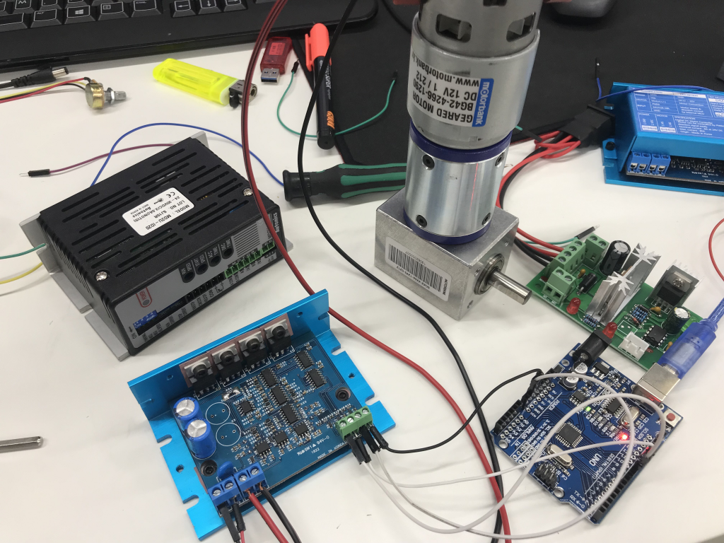
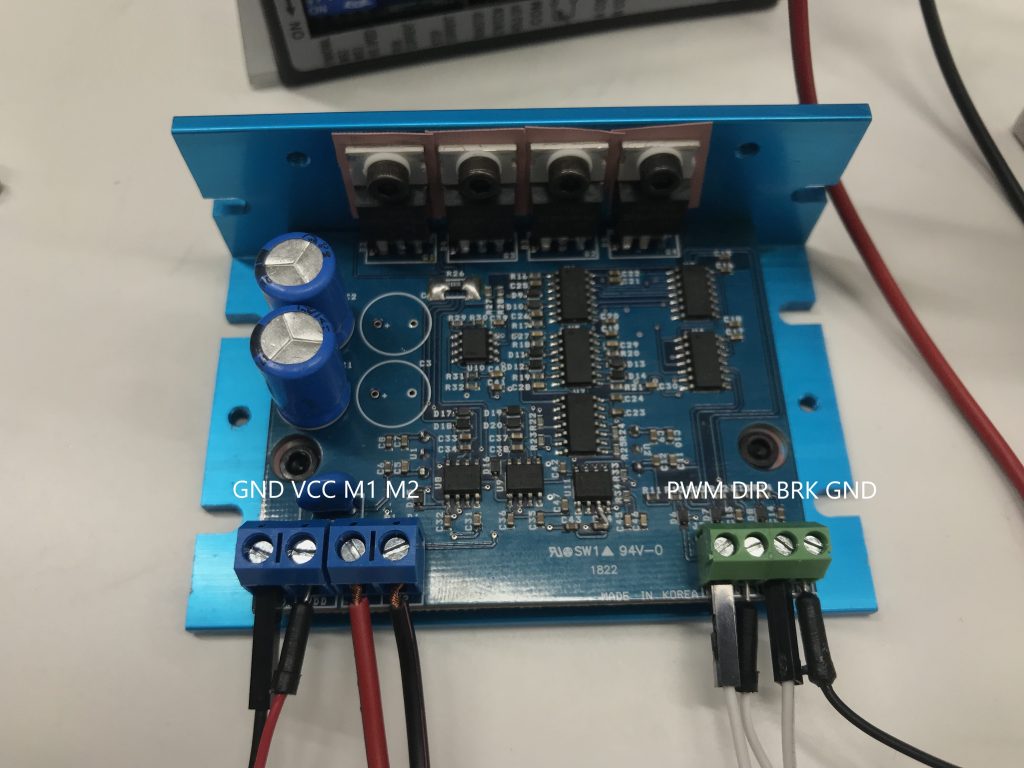
First, let’s look at the motor driver used. I used the DMD-200 motor driver. The pin map of the motor driver is shown below. The leftmost GND and VCC are the connecting parts of the power supply, and M1 and M2 are the connecting parts of the two poles of the motor. The PWM on the right side is connected to the PWM pin of the MCU, DIR is the terminal for changing the direction of the motor, and BRK is disconnected from the OPEN or HIGH state for the break function. The motor is driven when connected to GND or LOW. GND should be connected to GND of MCU.
For Arduino, the frequency is determined by the analog output (PWM) pin. The following table shows the case of Adu Uno. In the case of pins 5, 6, clock = 16,000,000 Hz, N = 64, f = clock / (512N) = 16000000 / (512X64) = 488.2812 for pins 9, 10, N = 64, f = clock / (256N) = 16000000 / (256X64) = 976.5625.
I used two software methods to change the frequency of the PWM pin. One of them is to change the value of TCCR0, the timer of atmega, to divide the existing allocated frequency to obtain the desired frequency. The other is to use the pwm library to change the frequency exactly as you would like.
And one important thing is to know the frequency of the motor driver. Normally, a motor driver needs a frequency of at least 10 kHz in order to drive a forward DC motor, and a normal motor driver has a frequency of 20 kHz.
void setPwmFrequency(int pin, int divisor) {
  byte mode;
  if(pin == 5 || pin == 6 || pin == 9 || pin == 10) {
    switch(divisor) {
      case 1: mode = 0x01; break;
      case 8: mode = 0x02; break;
      case 64: mode = 0x03; break;
      case 256: mode = 0x04; break;
      case 1024: mode = 0x05; break;
      default: return;
    }
    if(pin == 5 || pin == 6) {
      TCCR0B = TCCR0B & 0b11111000 | mode;
    } else {
      TCCR1B = TCCR1B & 0b11111000 | mode;
    }
  } else if(pin == 3 || pin == 11) {
    switch(divisor) {
      case 1: mode = 0x01; break;
      case 8: mode = 0x02; break;
      case 32: mode = 0x03; break;
      case 64: mode = 0x04; break;
      case 128: mode = 0x05; break;
      case 256: mode = 0x06; break;
      case 1024: mode = 0x7; break;
      default: return;
    }
    TCCR2B = TCCR2B & 0b11111000 | mode;
  }
}
The following functions can be used to change the frequency setting. If you want to use 3906Hz originally assigned pin 9 at 31250Hz, you can declare it as follows.
setPwmFrequency(9, 8);
To use the PWM library, download the library below.
pwm.h library download link
And, I used below code. The code says to turn around every three seconds, and it succeeded in normal operation. However, it sometimes causes malfunction due to sudden speed change or overload due to rotation direction change. This causes the motor to turn off once a second and to operate intermittently.
#include <PWM.h>

int32_t frequency = 20000;

int pwm = 9;
int dir = 10;

void setup() {
  Serial.begin(9600);
  InitTimersSafe();
  bool success = SetPinFrequencySafe(pwm, frequency);
  bool success2 = SetPinFrequencySafe(dir, frequency);
  if(success){
    pinMode(pwm, OUTPUT);
    pinMode(dir, OUTPUT);
  }
  else {
    Serial.println("Failed" );
  }
}

void loop() {
  pwmWrite(pwm, 125);
  digitalWrite(dir, HIGH);
  delay(3000);
  pwmWrite(pwm,125);
  digitalWrite(dir, LOW);
  delay(3000);
}
I think this is one of the most vital info for me. And i’m glad reading your article. But wanna remark on few general things, The web site style is wonderful, the articles is really excellent : D. Good job, cheers