
3D modeling of Universal Joint – Part 2

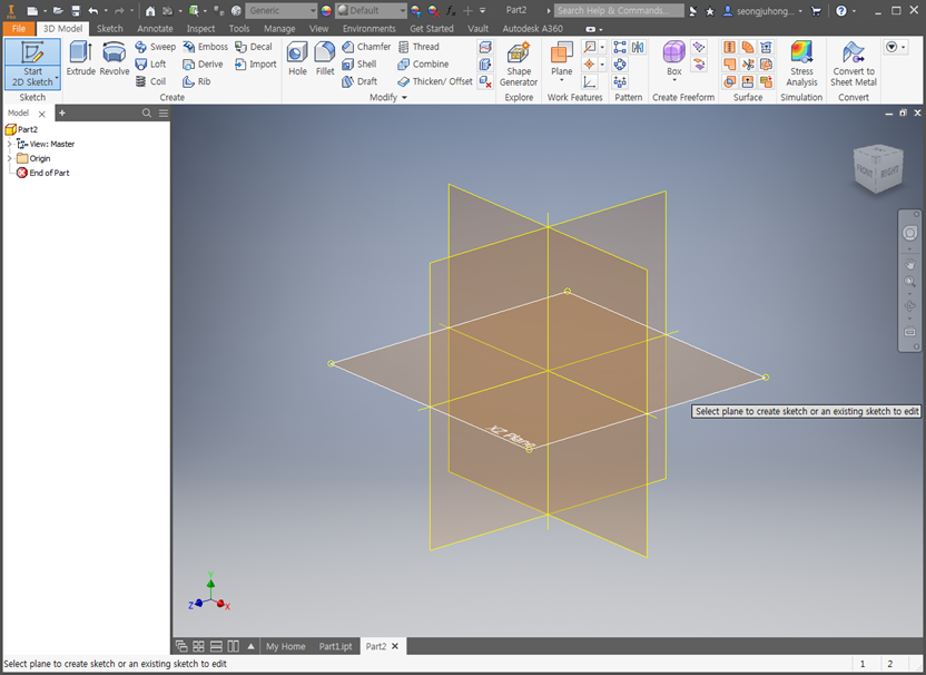
Select the XZ Plane
Sketch the circle with a diameter of 50mm

Extrude up to 60mm

Sketch on the YZ Plane

Using Arc Tangent for Sketch

Sketch as below

Extrude cut with both directions

Work Plane

Offset from Plane

Offset from Plane (42.124mm offset)

2D Sketch on the Work Plane

Extrude Cut

Fillet

Fillet with Radius of 1mm


Select YZ Plane and Start 2D Sketch

Draw a circle with a radius of 12.5mm

Extrude Cut with both directions


Select the top plane and Start 2D sketch

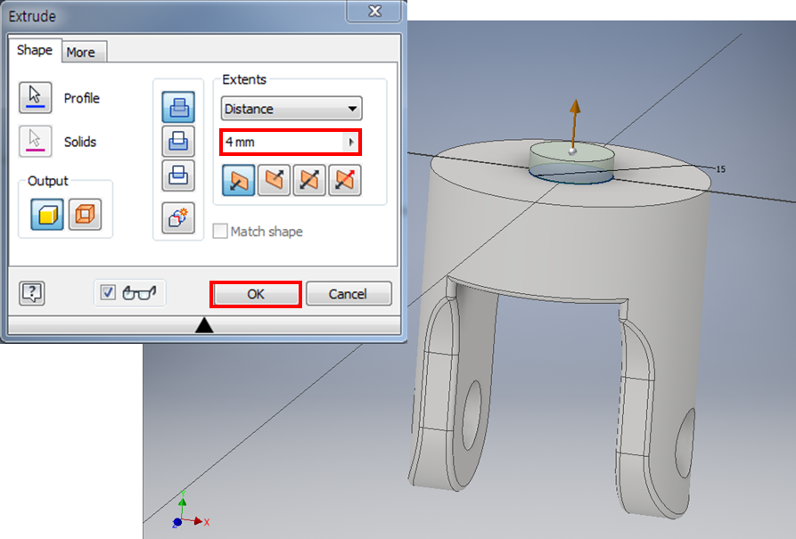
Draw a circle with a radius of 15mm

Extrude as 4mm
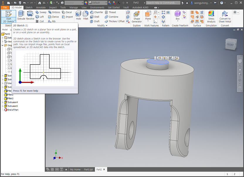
Select the top plane and Start 2D sketch
Draw a circle with a radius of 22.5mm

Extrude as 20mm

Select the top plane and Start 2D sketch

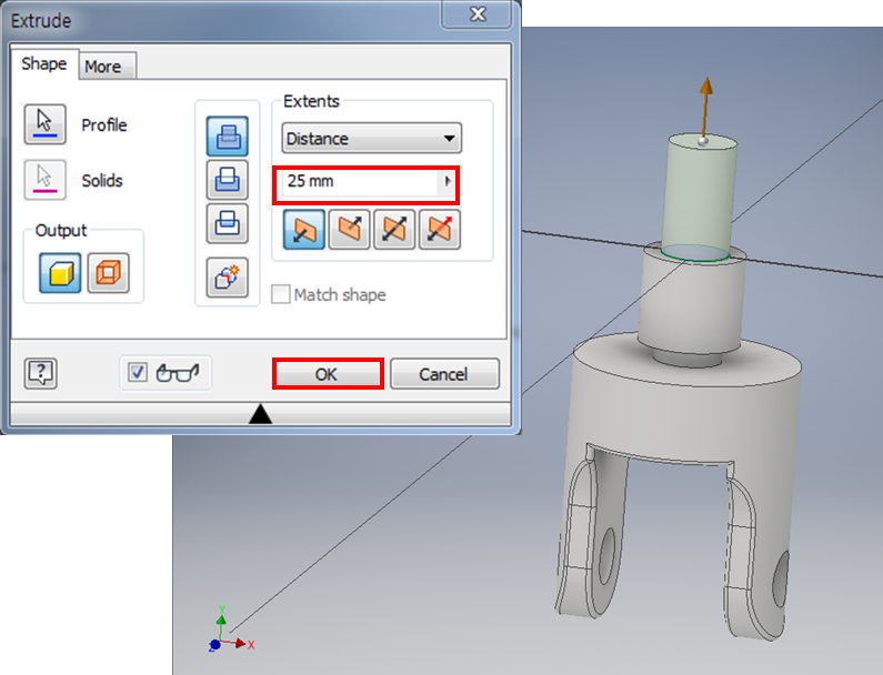
Draw a circle with a radius of 15mm

Extrude as 25mm
Fillet with Radius of 2.5mm


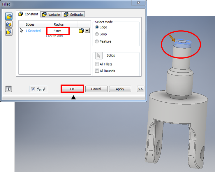
Fillet with Radius of 4mm
Chamfer with Distance of 1.5mm

Make Work Plane with top plane

Work Plane

Draw dotted line

Three Point Rectangle
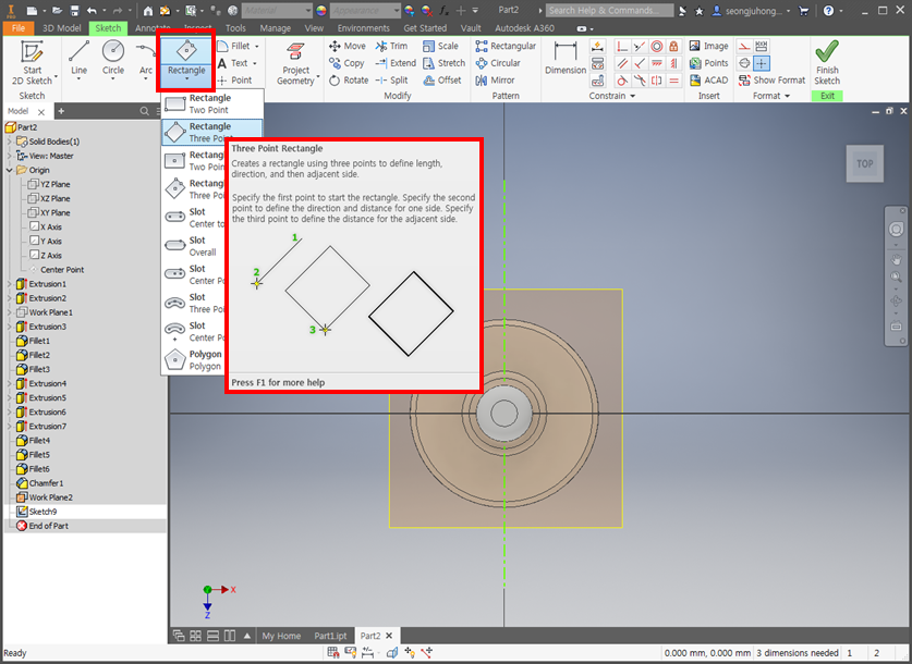
Draw Rectangle and Set the Dimension

Extrude as 2.5mm

Select the top plane and Start 2D Sketch

Draw a circle with diameter of 4mm

Extrude as 5mm

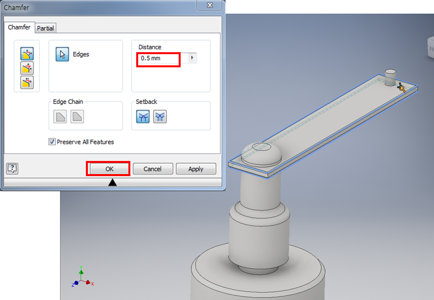
Chamfer with Distance of 0.5mm
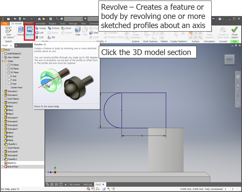
Select the YZ Plane and Start 2D Sketch


Revolve


Chamfer with Distance of 1mm

Setting Appearance as you want

Part 2 is completed, Save the file
